

If you manage a production facility, energy costs are undoubtedly one of the factors you monitor—whether through long-term contracts, spot-market settlements, or by planning investments in motor control drives, compressors, HVAC, or even photovoltaics (PV). Yet there is one item on the energy invoice that often goes unnoticed: charges for reactive energy.
At many industrial sites, penalties for reactive power—both inductive (motors, transformers) and capacitive (LEDs, UPSs, PVs, long cables)—can reach 30–40% on top of the active energy. That’s money leaving your budget every month without improving output, OEE, or product quality.
The good news: Reactive power can be measured, controlled, and optimized. And with a system like Nexen EMS, it stops being a mysterious penalty and becomes a lever for savings and reliability.
What is reactive power?
In most production facilities, the principles of active and reactive power are well understood, yet a concise recap is essential when addressing today’s increasingly dynamic power-quality environment. Active power (kW) is the part of electricity that performs real work—motor control drives, pumps, heating, cooling, and process equipment—while reactive power (kVAr) is the necessary companion that sustains magnetic and electric fields. Although reactive power does not contribute to output, it still circulates through conductors, transformers and switchgear, increasing current flow, thermal stress, and infrastructure loading.
Industrial plants draw both inductive and capacitive reactive power. The inductive share is still dominated by classic equipment such as:
- induction motors, pumps, compressors, and fans,
- transformers and distribution transformers,
- induction furnaces, welders, and other magnetically intensive loads.
At the same time, the rise of capacitive contributors has reshaped the reactive balance in many installations. This group is driven largely by:
- LED lighting systems with electronic drivers,
- UPS units and switched-mode power supplies,
- long and lightly loaded cable runs,
- PV inverters and other power-electronic converters.
As these sources increase, facilities increasingly operate with overlapping lagging and leading components. This creates a situation where network loading rises, losses accumulate, and compliance margins narrow—even when production demand remains unchanged.
To assess the balance between active and reactive power, industrial facilities rely on two key indicators. The first is tg φ (Q/P, reactive power/active power), which expresses the proportion of reactive power to active power and shows how much unwanted reactive component circulates in the network. The second is cos φ (P/S, active power/apparent power)—also known as the power factor—which indicates how efficiently the electrical system converts supplied energy into useful work. In Europe, including in Poland, industrial tariffs, the tg φ₀ value is the primary reference; it allows utilities to determine the effective power factor and evaluate whether a plant is operating within acceptable reactive power limits.
In Poland, utilities apply penalties when a facility exceeds defined thresholds for excessive reactive power. Typically, the penalty zone begins when tg φ₀ rises above 0.4, although some operators set stricter limits at 0.33 or even 0.2. These values correspond approximately to a cos φ in the 0.93–0.95 range, meaning that once the power factor drops below this level, the plant is considered to be drawing reactive power beyond the permitted allowance.
When these limits are crossed—whether due to fluctuating production loads, high PV-generation periods, or the increasing share of electronic equipment—the facility is immediately classified as operating outside the contractual reactive power range. The consequence is straightforward: The plant enters the penalty zone, and monthly electricity costs increase as additional charges for excessive reactive power are applied.
How excess reactive power impacts industrial facilities
Even in well-managed production environments, excess reactive power remains one of the most common—and most underestimated—sources of avoidable cost and electrical stress. While factory managers are familiar with the concept, the practical implications inside a modern facility have become more significant as load profiles diversify and power electronics proliferate. Reactive power fluctuations today are faster, more frequent, and more extreme than in conventional motor-dominated plants, and their consequences are felt across both operations and infrastructure.
The most immediate effect is financial. Utilities charge industrial customers for reactive energy whenever contractual limits are exceeded, and these penalties accumulate quickly. The structure of most tariffs means that even brief excursions—lasting minutes rather than hours—can translate into measurable kVArh over a billing period. Plants often pay not because of peak production but because of low-load periods, weekend operation, or PV-driven shifts in the Q/P ratio.
Beyond the penalties, excess reactive power has a direct technical impact. It forces higher current through the installation, which results in:
- increased thermal loading of cables and busbars,
- reduced transformer headroom and accelerated insulation aging,
- amplified distribution losses, especially in long internal networks.
These effects often remain unnoticed until they accumulate into voltage instability or equipment wear. Modern power-electronic devices—drives, PLC systems, robotics, UPS units—are particularly sensitive to voltage fluctuations and poor power factor conditions. As reactive loading rises, so does the likelihood of:
- nuisance tripping of protective devices,
- erratic behavior of sensitive controls,
- reduced lifetime of motors, transformers, and capacitors.
A growing portion of these issues is driven by partial-load operation and distributed generation. PV installations, in particular, reduce the active power drawn from the grid, causing tg φ to rise even if absolute reactive power stays constant. Combined with capacitive contributions from LEDs and long cable routes, plants often experience mixed reactive behavior that shifts throughout the day.
In short, the challenge is no longer the presence of reactive power—every facility has it. The real challenge is its variability, its interaction with modern loads, and the cumulative impact on both cost and network stability. Without continuous monitoring and dynamic correction, even well-designed installations drift into inefficiency and recurring penalties.

Nexen EMS: Turning reactive power from a cost driver into a controlled parameter
Nexen EMS brings structure and precision to reactive power management by providing continuous, real-time visibility into how inductive and capacitive components behave across an industrial facility. Instead of relying on monthly invoices or static compensators, the system measures key parameters—voltage and current, active and reactive power—with the granularity needed to identify when and where reactive power excursions occur.
With this measurement foundation in place, Nexen EMS enables active optimization rather than passive correction. It integrates directly with compensation infrastructure such as capacitor banks, hybrid compensators, and detuned filter systems and adjusts their operation dynamically. This allows the system to:
- add or remove capacitor-bank stages based on live tg φ trends,
- engage inductive elements to counter capacitive behavior from LEDs, UPS units, or PV inverters,
- balance reactive power across multiple zones to prevent over- or under-compensation,
- keep you within your contractual tg φ limit (e.g., tg φ ≤ 0.4), typically translating to cos φ ≥ 0.93–0.95, depending on the energy provider.
By stabilizing the reactive power profile, Nexen EMS also enhances overall electrical quality. Excess reactive power usually manifests as voltage fluctuations, transformer and cable overheating, reduced efficiency, and accelerated equipment wear. The system mitigates these issues by ensuring compensation is always aligned with the facility’s real-time operating conditions.
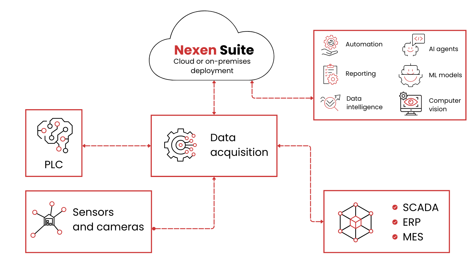
Fig 1. Nexen Suite architecture overview
Nexen EMS benefits
The resulting benefits are direct and measurable:
- elimination of reactive power penalties for both inductive and capacitive components,
- reduced transmission losses and improved voltage stability,
- extended equipment lifespan through lower thermal stress,
- full transparency and control, transforming reactive power from a hidden overhead into an optimized performance parameter.
With Nexen EMS, reactive power management becomes a proactive, automated, and financially meaningful part of energy strategy—ideal for facilities where load conditions change quickly and accuracy matters.
From analysis to full deployment: How we implement Nexen EMS
If you want to evaluate Nexen EMS for reactive power optimization, we can prepare a proof of concept (PoC) tailored to your facility. The process is straightforward and based on real technical verification:
- On-site assessment/technology audit
We examine your electrical infrastructure, identify suitable installation points, and check whether existing meters can be used. - Review of available data
We verify what reactive power measurements you already have; many facilities only see aggregated tg φ, so the PoC often becomes the first moment to capture detailed power factor and phase-shift data. - Defining the measurement architecture
Together we determine how many meters are needed, where the central unit will be placed, and how the data will be collected. - Deployment of the PoC setup
We install and configure Nexen EMS to monitor your actual loads, compensation systems, and operating conditions. - Testing, validation, and optimization
We analyze tg φ, cos φ and reactive power patterns, fine-tune the setup, and confirm measurable improvements before scaling.
Ready to see Nexen EMS in action? Start with a PoC and evaluate the benefits in your own facility. Contact us at sales@fabrity.pl.